Hydraulic systems on agricultural machinery are the backbone of efficient field operations. Properly adjusting the pressure settings in a tractor’s hydraulic circuit enhances implement performance, extends component life, and protects both operator and machine from damage. This guide walks through the essential steps, from understanding basic principles to fine-tuning the relief valve and confirming optimal flow.
Understanding Hydraulic Systems
Fundamentals of Tractor Hydraulics
At its core, a tractor’s hydraulic system transforms mechanical engine power into fluid power. High-pressure oil drives cylinders and motors that lift, tilt, and move heavy loads. Familiarity with major components such as pumps, hoses, control valves, and filters underlies every successful adjustment. The system’s ability to maintain consistent pressure and flow hinges on precision engineering and routine maintenance.
Key Components
- Pump: Suction from the oil reservoir supplies the pump, which pressurizes fluid for distribution.
- Relief valve: A critical safety device that limits maximum system pressure to prevent damage.
- Control valve: Directs oil to various hydraulic circuits, enabling implements like loaders, plows, and mowers.
- Filters and reservoir: Clean oil ensures longevity; the reservoir stores fluid and aids heat dissipation.
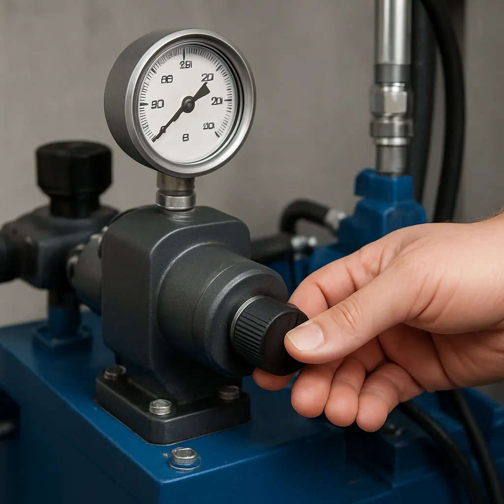
- Gauges and sensors: Provide real-time feedback on system pressure and temperature.
Pre-Adjustment Preparation
Safety Precautions
Before touching any hydraulic component, always engage the tractor’s parking brake, lower implements to the ground, and shut off the engine. Relieve residual pressure by cycling the joystick or lever in all directions. Wear protective gloves and eyewear, and keep body parts clear of potential high-pressure leaks. High-pressure oil can pierce skin, so inspect hoses and fittings for damage before beginning work.
Required Tools and Equipment
- Hydraulic gauge set matched to your tractor’s specifications
- Wrench set for valve adjustments
- Clean lint-free rags
- Manufacturer’s service manual for reference pressures
- Thread-locking compound (if specified by the manufacturer)
Documentation and Reference
Consult the service manual for the recommended relief valve setting. Record current readings as a baseline. A maintenance log helps track changes over time, revealing trends like creeping pressure that might indicate worn components or contaminated oil.
Step-by-Step Pressure Adjustment
Locating the Relief Valve
The main relief valve typically resides near the hydraulic pump or within the control block. Look for a hex-headed screw with a lock nut. Some tractors feature remote valves at the rear linkage; ensure you’re working on the primary circuit if targeting implement performance.
Initial Pressure Check
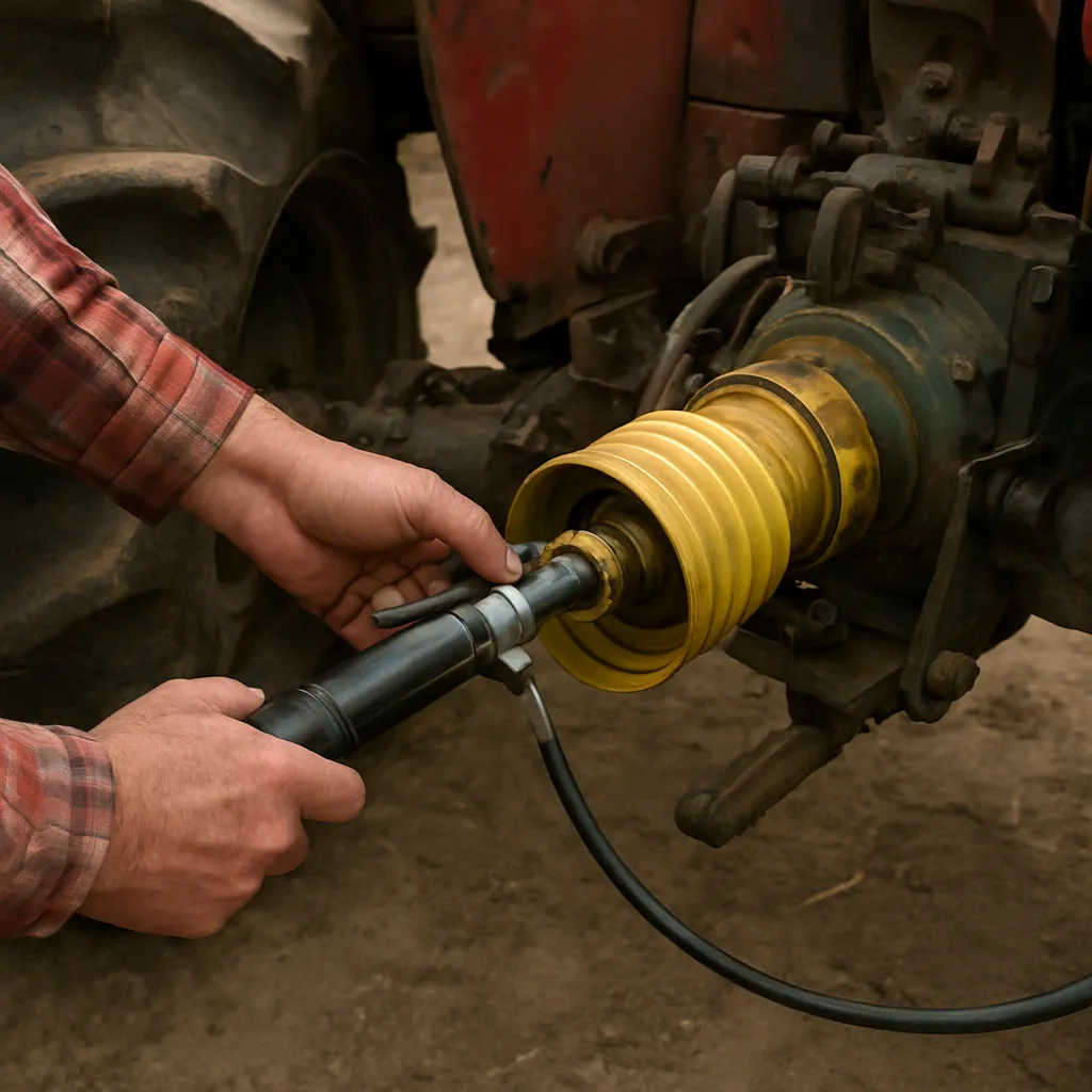
1. Attach the gauge to the test port or T-fitting on the hydraulic line.
2. Start the engine and let it idle to reach operating temperature.
3. Cycle the hydraulic controls to purge air and stale fluid.
4. Observe the gauge reading; this is your starting pressure.
Adjusting the Relief Valve
1. Loosen the lock nut securing the adjustment screw, ensuring you don’t twist downstream components.
2. Turn the adjustment screw in small increments (clockwise to raise pressure, counterclockwise to lower it).
3. After each quarter turn, retighten the lock nut lightly, then recheck the pressure.
4. Aim for the manufacturer’s recommended setting, typically within ±50 psi tolerance.
Fine-Tuning and Verification
Once the target pressure is reached, cycle all implements under load. Observe any pressure spikes or drops. If performance lags under heavy load, increment pressure slightly and retest. Confirm that the relief valve operates at or just above the set point to protect the system from overload.
Troubleshooting Common Issues
Pressure Fluctuations
- Fluctuating readings often indicate air in the lines. Bleed the system by fully extending and retracting cylinders several times.
- Worn pump components can cause inconsistent pressure. Inspect internal pump wear rings and bearings.
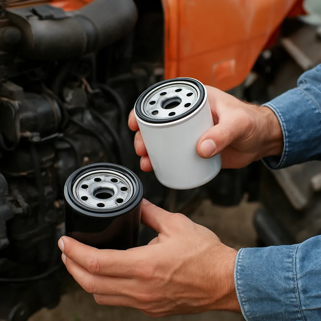
- Clogged filters restrict flow, leading to erratic readings. Replace the hydraulic filter regularly.
Valve Drifting
If the relief valve setting creeps over time, the spring or seat may be worn. A minor spring fatigue can lower the pressure threshold. Replace or rebuild the valve assembly using genuine parts to maintain correct calibration.
Unstable Flow to Implements
Flow control valves or priority valves can malfunction, diverting oil incorrectly. Check that auxiliary valve settings match implement requirements. Undersized hoses or fittings can also starve circuits, so ensure component sizing aligns with the hydraulic pump’s output.
Maintaining Optimal Performance
Routine Inspections
Implement a regular inspection schedule. Check oil level and condition weekly, looking for foam, discoloration, or fumes. Inspect hoses monthly for abrasion, cracking, or bulging.
Long-Term Care
Change hydraulic oil at intervals recommended by the manufacturer, typically every 1,000 engine hours. Use only approved oil grades—mismatched viscosity or additive packages can harm seals and valves. Periodically test system pressure to detect slow leaks or component wear before major failure.
By following these procedures, you can confidently adjust and maintain your tractor’s hydraulic pressure settings, ensuring reliable operation in the field and extending the service life of critical components.