Diagnosing hydraulic leaks on tractors is essential for maintaining optimal performance and extending the life of critical components. By understanding the root causes of leaks and applying systematic diagnostic methods, operators can prevent costly downtime and safety hazards. This guide explores the key steps and tools needed to identify and repair hydraulic leaks in agricultural machinery.
Understanding Tractor Hydraulic Systems
Tractor hydraulics rely on a network of pumps, hoses, valves, and cylinders to power implements such as loaders, plows, and balers. A typical system includes a hydraulic pump driven by the engine, a reservoir to store fluid, control valves for regulating flow, and various actuators. Pressure is maintained by relief valves, protecting the system from overload. When any component fails or seals degrade, fluid escapes, reducing efficiency.
Key components to familiarize yourself with:
- Hydraulic pump – generates flow and pressure.
- Reservoir – stores fluid and allows for air separation.
- Control valves – direct fluid to different circuits.
- Cylinders – convert fluid pressure into mechanical force.
- Hoses and fittings – transport fluid under high pressure.
Proper understanding of these parts and how they interact under load is the foundation for effective leak diagnosis.
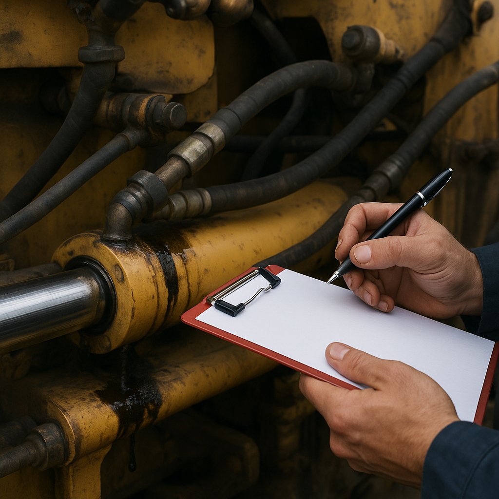
Initial Visual Inspection
Begin every diagnostic procedure with a thorough visual check. This quick assessment can reveal obvious leaks and potential trouble areas before more invasive testing.
- Inspect hoses for cracks, bulges, or abrasions. Look for faded or brittle sections.
- Check fittings and connections for signs of seepage or fluid accumulation.
- Examine cylinder rods and seals; even a small drip can indicate seal wear.
- Observe the reservoir cap and breathers for foaming or contamination.
- Scan around pumps and motors for residue that may point to gasket failures.
Use a clean rag or absorbent pads to gently wipe suspect areas; newly exposed fluid will stand out against a dry surface.
Pressure Testing Procedures
Pressure testing helps pinpoint leaks that are not visible under no-load conditions. By applying controlled force, you can stimulate leak paths in fittings, hoses, or valves.
Using a Test Gauge
Attach a calibrated pressure gauge to a test port nearest the pump. Run the engine at mid-range RPM and operate hydraulic controls sequentially:
- Raise and lower implements to alternate pressure spikes.
- Note any sudden drops or fluctuations on the gauge.
- Compare readings against manufacturer specifications.
Significant pressure loss under load indicates internal leaks or blocked circuits.
Leak-Down Test
Isolate individual circuits by closing selector or directional valves. Pressurize one section at a time and observe the rate of pressure decay:
- Rapid drop indicates a serious leak past a seal or within a valve spool.
- Slow decline may point to micro leaks in hose joints or adapter threads.
Identifying Common Leak Sources
Hydraulic leaks usually occur in predictable areas: hoses, fittings, seals, and valves. Recognizing patterns can speed up troubleshooting.
- Hose Fittings – Vibration can loosen crimped ends or O‐ring seals.
- Pump Shaft Seal – Worn shaft sleeves allow fluid to escape at the drive interface.
- Cylinders – Rod seals fail from scoring, heat, or contamination.
- Control Valves – Internal wear leads to bypassing and external seepage.
- Quick-Connect Couplers – Dirt and corrosion compromise sealing surfaces.
Maintain an inventory of replacement parts such as gaskets, replacement hoses, and seal kits. This ensures rapid repair once the leak source is confirmed.
Advanced Diagnostic Tools
For more elusive leaks, specialized instruments reveal hidden issues without full disassembly.
- Infrared Thermometer – Detects hot spots where friction indicates internal leakage.
- Ultrasonic Leak Detector – Picks up high-frequency noises from fluid escape under pressure.
- Hydraulic Cleaners – Removes sludge and varnish that mask small leaks.
- Borescopes – Allow internal inspection of valves and pumps through small ports.
These tools improve the accuracy of your diagnosis and reduce guesswork when tackling complex systems.
Repair and Preventive Measures
Once the leak source is located, follow these best practices for a durable repair:
- Depressurize the system completely before disassembly to avoid injury.
- Clean mating surfaces with a lint-free cloth and solvent to ensure proper seating of seals.
- Use the correct torque specifications for fittings; over-tightening can damage threads and O‐rings.
- Replace hoses at regular intervals based on operating hours and exposure to abrasion.
- Install high-quality filters to reduce contamination that accelerates seal wear.
Regular preventive maintenance, including fluid analysis for wear metals, helps detect emerging issues before visible leaks develop.